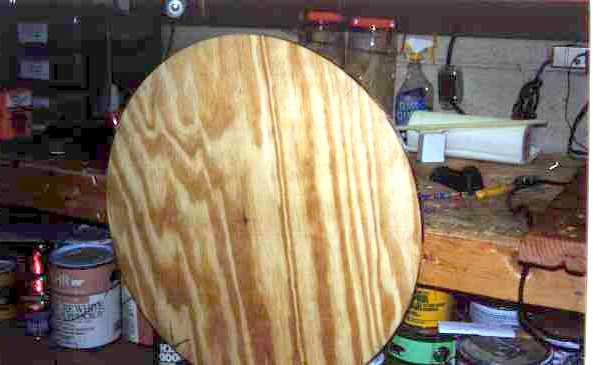
 Azimuth
circle ready for molding.
Azimuth
circle ready for molding.3/18 The big decision necessary here is to whether mold the gear on the existing ground board or go with a new ground board. Starmaster scopes use a circular ground board and all that would be necessary would be to cut the groove into the edge. In keeping with one of the design considerations, that of keeping the scope as stock as possible, the decision to make a new ground board was an easy one. We spent a couple hours today cutting out and grooving a new ground board/gear. This is made out of a 1/2 sheet of 3/4" B-C plywood. As with the altitude sector, it was cut on a 10" bench mount table saw.
Grooving it was more difficult because a plunge cut was necessary before actually cutting the groove. In the case of the altitude sector, there was a flat area that was turned towards the table saw blade. This made it possible to set the height and angle of the blade before actually cutting the wood. Once set, the piece was rotated to bring the circular edge into contact with the blade.
With a circular piece, it was necessary to have the edge of the board flat on the top of the saw table. This makes it impossible to set the depth and angle of cut before the blade enters the wood. This time a preliminary groove was cut with a small, battery operated Skilsaw. I would have been quite unable to perform this operation, but it looked easy when done by the skilled hands of Harry. He set the saw to the approximate depth and angle of cut and cut about 4 inches of groove while holding the saw in his hand. We were then able to lower this groove onto blade of the table saw and make the final 360 degree cut. If this doesn't explain the operation clearly (which doesn't surprise me!), leave me e-mail and I'll try to do better. I can see two methods of attempting to mold this large gear. The altitude sector was done as one molding of approximately 40 inches. I can attempt to do the same thing - two 40" sections or attempt to make one long section of 72" and then a short section of 10 inches. Since the altitude sector came out so well, the first attempt will be by molding as large a section as possible and then filling in the remaining few inches with a second molding.
The molding process will take place tomorrow. I hope to have some more pictures online before next weekend (3/25). The altitude sector has had the cutouts made to lighten weight and it is just about finished.
Azimuth
circle ready for molding.
3/19 First molding attempt has been completed. Now just a matter of waiting 24 hours to see what turns up. I didn't mix up enough JB, so rather than molding 4/5ths of the wheel, it ended up being only about 3/5ths. This means I have a much bigger area to cast to complete the 360 degree circuit. Will report tomorrow when the threaded rod is removed from the JB Weld.
|
|
3/20 While it may not be pretty, it might be usable. The first problem is the plywood itself. For the altitude sector, birch ply was used. This is multiple layer plywood of at least 8 or 9 plies. The normal B-C plywood is only 5 plies thick. The birch seems to be held together with a much stronger glue than the regular ply. The result is that there was some breakage along the edge of the groove of the regular ply. It doesn't appear that this is so bad the gear will not work, however. I will try filling in the broken areas with plastic wood to protect the JB from being damaged by impact when the scope is transported. I plan on molding the other part of the gear tonight or tomorrow and will evaluate the finished product in another day or two.
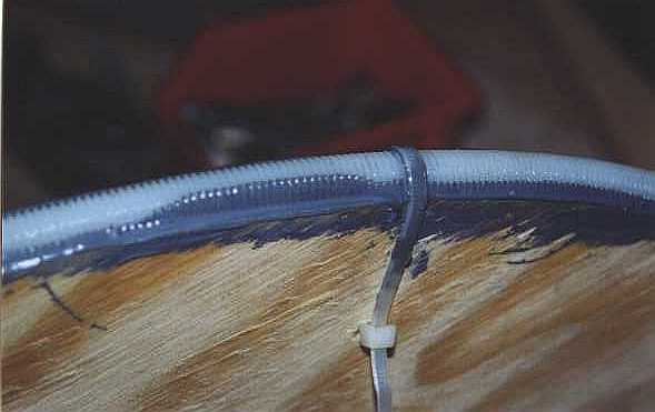
 Here
you can see where the plywood broke as the rod was removed.
Here
you can see where the plywood broke as the rod was removed.
3/21 The second molding of the gear is underway. Will find out tomorrow if it worked or not. One problem I anticipated was getting the threads to match on both sides of the newly cast area. This turned out not to be a problem at all. Technique was to match the threaded rod with the cast threads on one side, secure the rod in place with tie wraps and then force the rod into the JB Weld. As I reached the other side of the gap, it was a simple matter to press the rod into the JB a bit - enough to get the threads to match. With a 13 pitch rod, you only have to adjust the rod by 1/26th of an inch to get the teeth aligned. The unset JB gives you plenty of latitude for this adjustment.
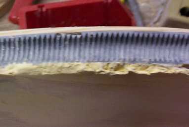
3/25 The casting for the second part of the azimuth gear went very well! Not perfect, but the gear appears to be usable.
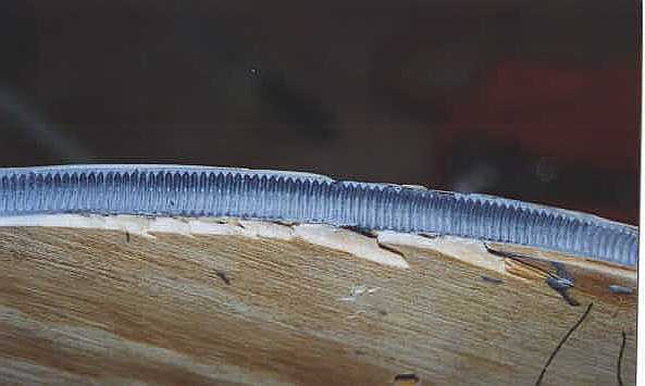
 This shows where the new casting
(lighter gray) and the original meet. It's not pretty but it should
work. I picked up a digital camera which should make posting images
a lot easier!
This shows where the new casting
(lighter gray) and the original meet. It's not pretty but it should
work. I picked up a digital camera which should make posting images
a lot easier!
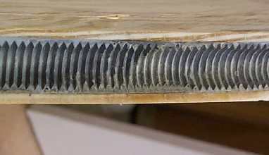
This is a badly focused shot of the worst area of the azimuth gear. It is easy to see where the wood pulled out when removing the threaded rod. I have attempted (not too successfully) to fill in a bit with plastic wood.