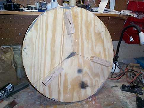
| 3/28 Spent some time today working on the ground board and altitude sector. As you can see from the image below, some feet have been added to the bottom of the board. These are made from a double thickness of 3/4" birch ply - glued and screwed together and then screwed to the bottom of the board. The whole thing will look a lot better once it has been painted! |
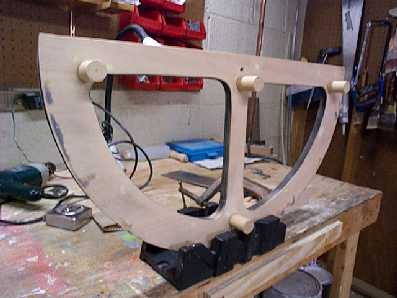
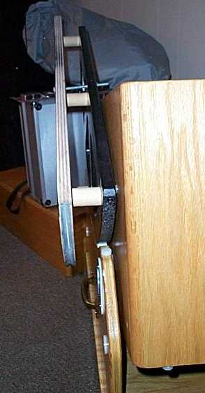
| The image on the right shows standoffs mounted on the altitude sector. This sector will stand 1.5" out from the altitude bearing. The spacing is necessary to give room to mount the stepper. The standoffs were made out of a piece of 1" diameter hardwood doweling. They were cut to length using a cheap, plastic miter box and a jig made from a C-clamp and piece of plywood to keep the cuts uniform. You can see this simple setup in the photo below left. For those woodworkers out there, this is all second nature. For some of us, it's new ground! |
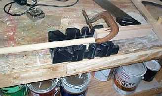 C-clamp holds a piece of wood the proper distance
away from the cut. This will insure each piece of doweling will
be the same length.
C-clamp holds a piece of wood the proper distance
away from the cut. This will insure each piece of doweling will
be the same length.
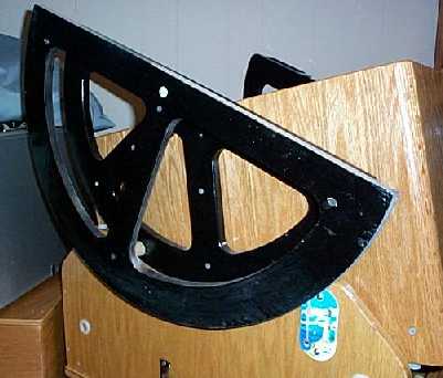
| Here are two photos of the altitude sector in place along side the altitude bearing. You can see the standoffs in the right hand photo. Eventually the standoffs will be screwed to the altitude bearing, but this will come after the sector is fully painted and the stepper assembly is complete. |
4/29 Today was frustrating while being a learning experience. Took all the parts over to Harry's and we tried start putting them together. Let me take you through the day and show you what we did wrong (mostly everything) and what we learned.
The plan has been to mount bearings on a new ground board, put a sheet of metal on the bottom of the rocker box and drive the gear. First thing, the bearings didn't work at all! Here is another picture of the bearing:
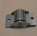 The
bearing we tried to use is 1.5 inches between the two screw holes
and the cylinder is 7/8th inches long. The cylinder just rides
a shaft and the motion is not like that found in a ball or roller
bearing. We decided to try mounting the bearing upside down from
the way it is shown in the picture. The reason for this is the
metal that comes almost to the top of the cylinder. There is very
little clearance between the metal ear and the top of the cylinder
and I worried about wear and the metal scraping the bottom of
the rocker box.. Mounted upside down, there is a good quarter
inch of cylinder projecting above the frame of the bearing. We
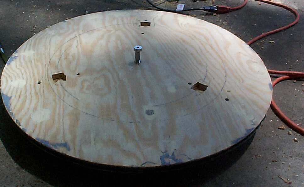
used a 1 1/4" spade bit to drill out a hole and then cut
away the edges with a chisel to let the bearing set in. Here's
the ground board with the holes drilled and chiseled. We have
also drilled out the 1/2" center hole for the encoder mounting
bolt (and it holds the rocker box to the ground board!) The picture
on the right shows one of the bearings dropped into the hole.
The
bearing we tried to use is 1.5 inches between the two screw holes
and the cylinder is 7/8th inches long. The cylinder just rides
a shaft and the motion is not like that found in a ball or roller
bearing. We decided to try mounting the bearing upside down from
the way it is shown in the picture. The reason for this is the
metal that comes almost to the top of the cylinder. There is very
little clearance between the metal ear and the top of the cylinder
and I worried about wear and the metal scraping the bottom of
the rocker box.. Mounted upside down, there is a good quarter
inch of cylinder projecting above the frame of the bearing. We
used a 1 1/4" spade bit to drill out a hole and then cut
away the edges with a chisel to let the bearing set in. Here's
the ground board with the holes drilled and chiseled. We have
also drilled out the 1/2" center hole for the encoder mounting
bolt (and it holds the rocker box to the ground board!) The picture
on the right shows one of the bearings dropped into the hole.
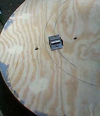
Next on the agenda was pulling the original groundboard off the rocker box and putting a piece of sheet steel over the Formica. This was a simple process that only required drilling out the 1/2" center bolt hole and screwing the corners of the steel down. Here's what it looked like before the 4 corner screws were installed.
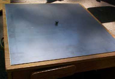 It was
time to fit the rocker box together with the new ground board
and see how it all worked!
It was
time to fit the rocker box together with the new ground board
and see how it all worked!