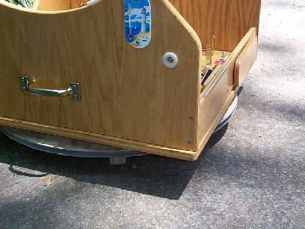
4/29 (Continued) Ok, it was time to mount the rocker box on the new ground board and see how everything worked. In a word - TERRIBLE! There was absolutely no sense of smoothness of motion of the bearings against the bottom plate. In fact, the original Teflon against Formica was far, far smoother in motion than the new setup. I expect the reason for this is twofold - first, these are really not bearings, but rollers used in drawers and very crude. Secondly, the 7/8th inch width of the cylinder is probably causing friction because the outer end will have to be turning a bit faster than the inner end as the rocker box is turned. The bearing would probably work just fine for linear motion, but it doesn't work worth a flip for circular. Here's a shot of the new ground board with the rocker box on top:
All was not lost, however. Finally matching these two pieces gave us an opportunity to start working on how the azimuth motor will be mounted. It looks as if the rocker box will have to sit a bit higher than it is in the photo. The motor is approximately 2.5" square at the faceplate and there really is no room to mount the motor as the scope is configured. We quickly mounted the bearings on 3/4" plywood blocks to elevate the rocker box (very quick and dirty and definitely not how the finished product will look or work!
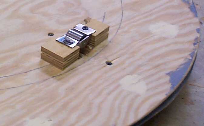
Bending a piece of 1/8" aluminum, we quickly fabricated a bracket to hold the azimuth motor in place and actually turned the rocker box a bit! Following a suggestion from several people, I used a piece of hose to act as the coupling between motor and threaded rod. This, too, was completely unsatisfactory. While it's obvious that a lot more work needs to be do on the bearing surfaces and some sort of linkage between the rod and motor shaft. I will give the wooden coupling a try next time we work on the project.
While much of the work today feels like a failure it still gave some practical experience of how NOT to do things! For the next assault I think we will mount blocks on the ground board and put Teflon on the blocks and try that. As I said earlier, the motion of the present system is very smooth and easy turning. While everyone seems to go with bearings, it is possible that Teflon on Ebony Star may prove usable. If not, a more conventional arrangement with mounted ball bearings will be tried.
Next time around I will also try my original wooden coupler for the motor-rod connection. The rubber hose didn't work very well. It was impossible to get the rod and motor shaft to hold concentric positions. I expect it doesn't work in my case because of the different diameters of the 1/2" rod and 1/4" motor shaft. This will be another area for exploration and experimentation.
4/30 Spent another couple of hours over at Harry's working on both his and my scopes. He has a Coulter 13.1" scope that is being renovated a bit with a new rocker box, coat of paint and some other improvements. Well deserved too, I might add, after 9 or 10 years of observing! Most of the work done on the computerization project was cutting out a few blocks of wood and fabricating motor mounts. The blocks of wood will go on the ground board to elevate the rocker box enough to let the azimuth motor fit. The blocks were cut out of the Baltic birch plywood used for the altitude bearing. The motor mounts were made from a 6' x 3" strip of 1/8th inch aluminum plate. aluminum is nice because you can do most of your fabrications with woodworking tools. We cut the strip with a table saw and used a router to cut adjusting slots in the pieces. The motor mounts were formed by holding one end in a large bench vise and beating the other end over with a rubber mallet. They are crude compared to something done on a milling machine, but they should work. One of these days, some of these parts might be farmed out to a small machine shop to get them nicely made.
Harry also had a chunk of Teflon, so we cut out 3 2" x 2" squares. As I mentioned above, the next attempt will use Teflon on Formica for the az. bearing surface. If it doesn't work, we'll explore other avenues.
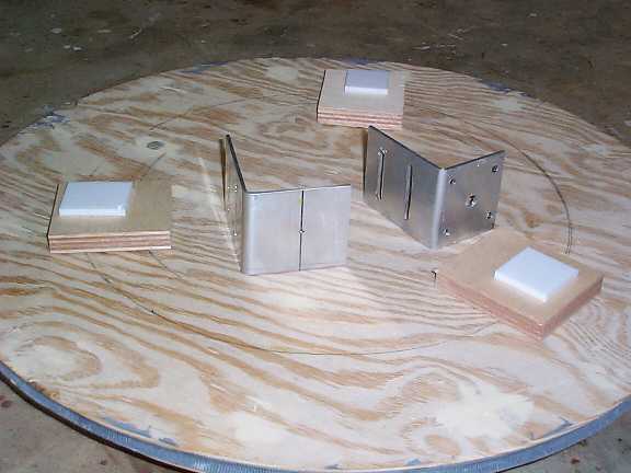 The
wooden pieces, Teflon blocks and motor mounts sitting on the ground
board.
The
wooden pieces, Teflon blocks and motor mounts sitting on the ground
board.
The next job will be mounting the altitude gear on the side of one of the altitude bearings and installing the motor and threaded rod. Along with this will facing the altitude bearings with aluminum and putting the little bearings (small cousins to the ones that did NOT work for the ground board!) to take the place of the Teflon. After the experience with the big bearings, I don't have a really good feeling about this, but will see what happens when we reach that point.
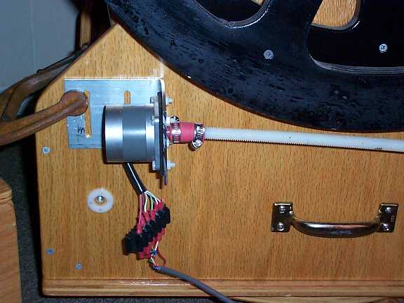
5/1 Didn't do much today. I did mount on of the motors into the altitude motor bracket and used a C clamp to see how it would position against the rocker box. I also mounted the altitude bearing on the side of the rocker box. If you look at the photo below, you will notice the red hose acting as a coupling between motor and rod. Yes, I've gone back to that, but will be mounting a bearing in a block at the end of the threaded rod to help support the rod. With a supported rod, the hose coupling might work.
I am planning on using a wing nut on a carriage bolt in the rear slot on the motor bracket and a nut and bolt on the front slot. The winged nut will allow me to loosen up the motor mount and drop it down a half inch or so. This should pull the threaded rod out of engagement with the alt gear so the scope can be moved by hand while setting it up and taking it down. The Starmaster has a removable primary. Setup is done with the scope pointing straight up while the truss tubes and upper tube assembly are installed. The scope is then pointed horizontal to gain access to the back of the mirror box to insert the mirror/cell. I need to have the ability to move the scope freely in altitude during this process and, so, need to be able to disengage the gears.
If you look closely at the photo you may notice the black between the face of the motor and the mounting bracket. This is a piece of 1/8" thick rubber I found in the plumbing section of my favorite hardware store. You will also see the motor is held on with nylon machine screws and nuts. These are efforts to help reduce noise and vibration when the motor is running.