Removal of the fork arms:
My preference here is to remove one fork arm from the telescope and drive base while leaving the other fork arm attached to the scope. Lay the telescope on a flat surface (padded with a towel or blanket) and remove the 2 screws holding the fork arm to the tube assembly and the 2 bolts holding the fork arm to the drive base.
Turn the scope assembly over and remove the 2 bolts from the other side of the drive base. It is now possible to lift the scope and remaining fork arm off the drive base.
Turn the drive base over and remove the 5/8th inch bolt from the bottom.
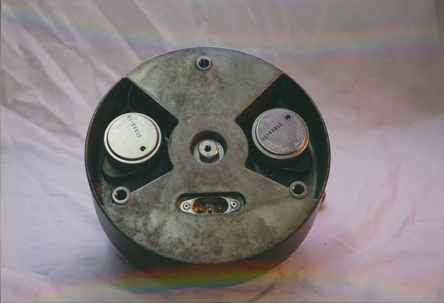
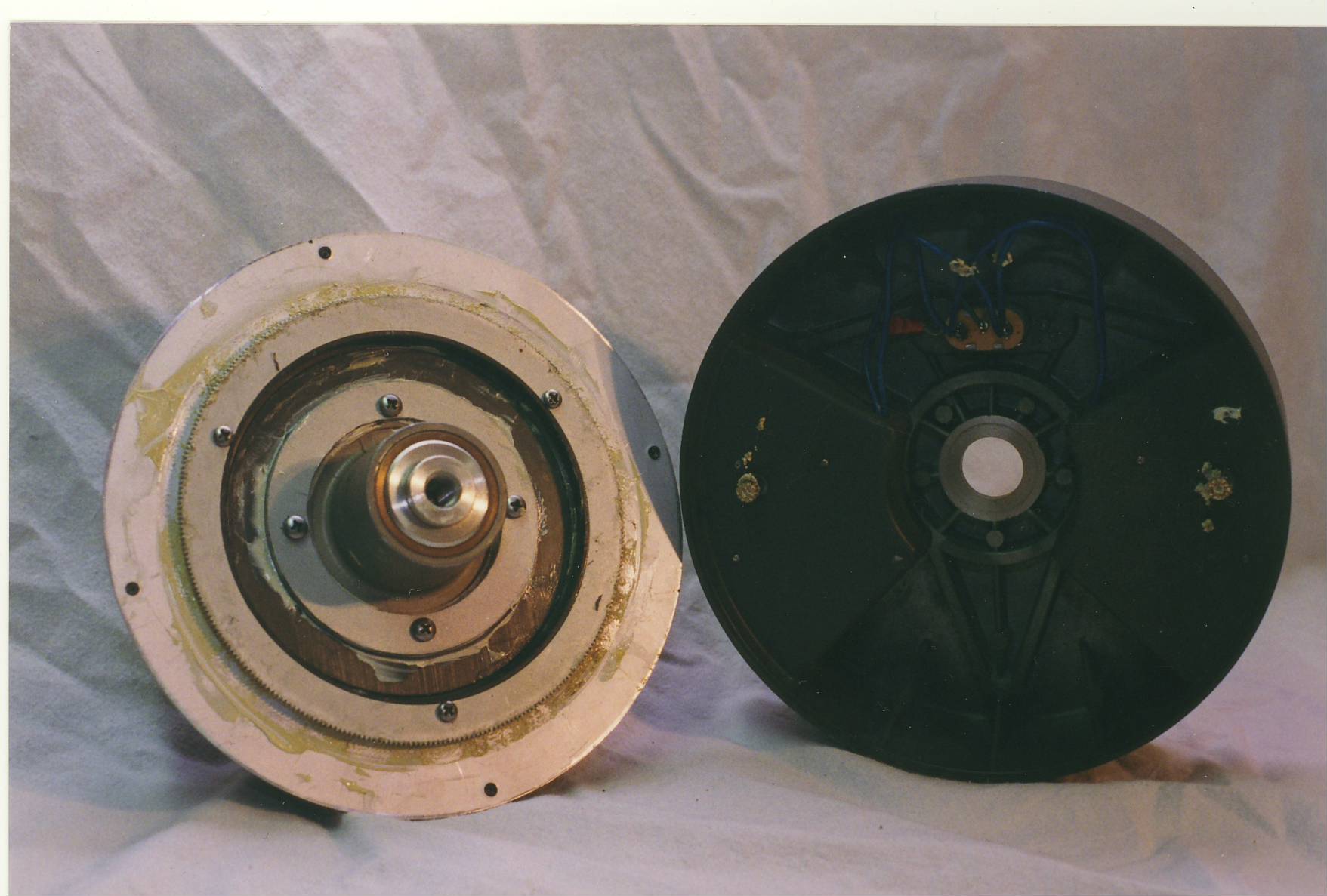
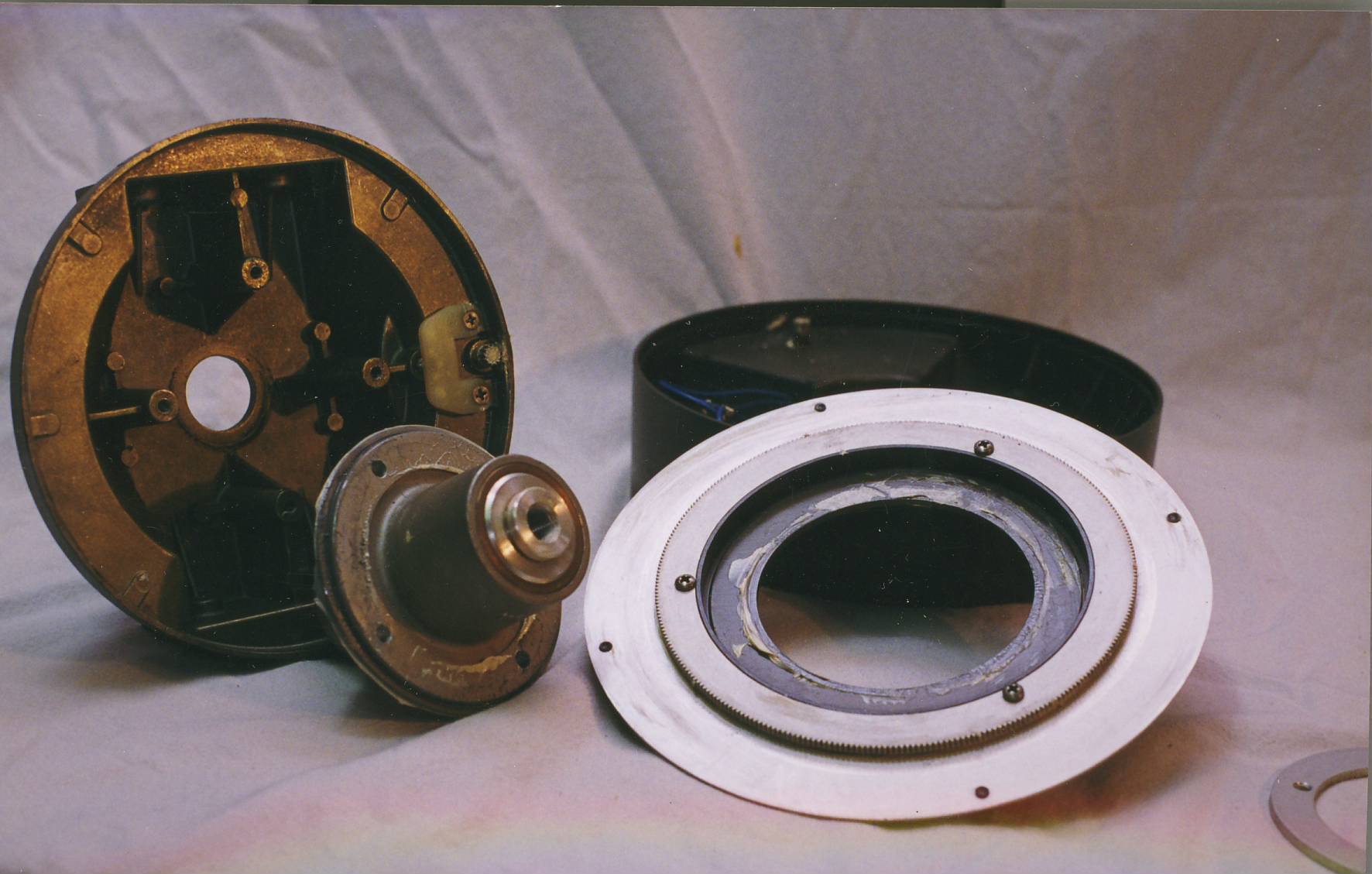
The drive base will come apart into 2 pieces - the base bottom with the motors and the base top with setting circle assembly, polar axis and top plate still attached.
Removal of the 4 screws holding the ring around the polar axis will separate the setting circle and polar axis assembly from the top plate.
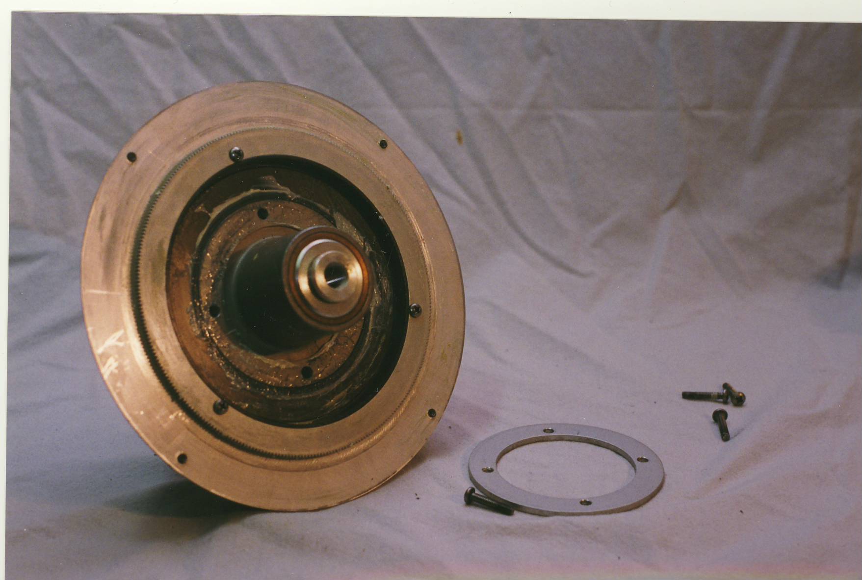
The polar axis bearings can be pulled by removing the c-clip. This is pretty much a sealed unit and I have never found it necessary to take the axis apart. If it does not turn freely inside the housing, you might consider removal. Otherwise, leave it alone.
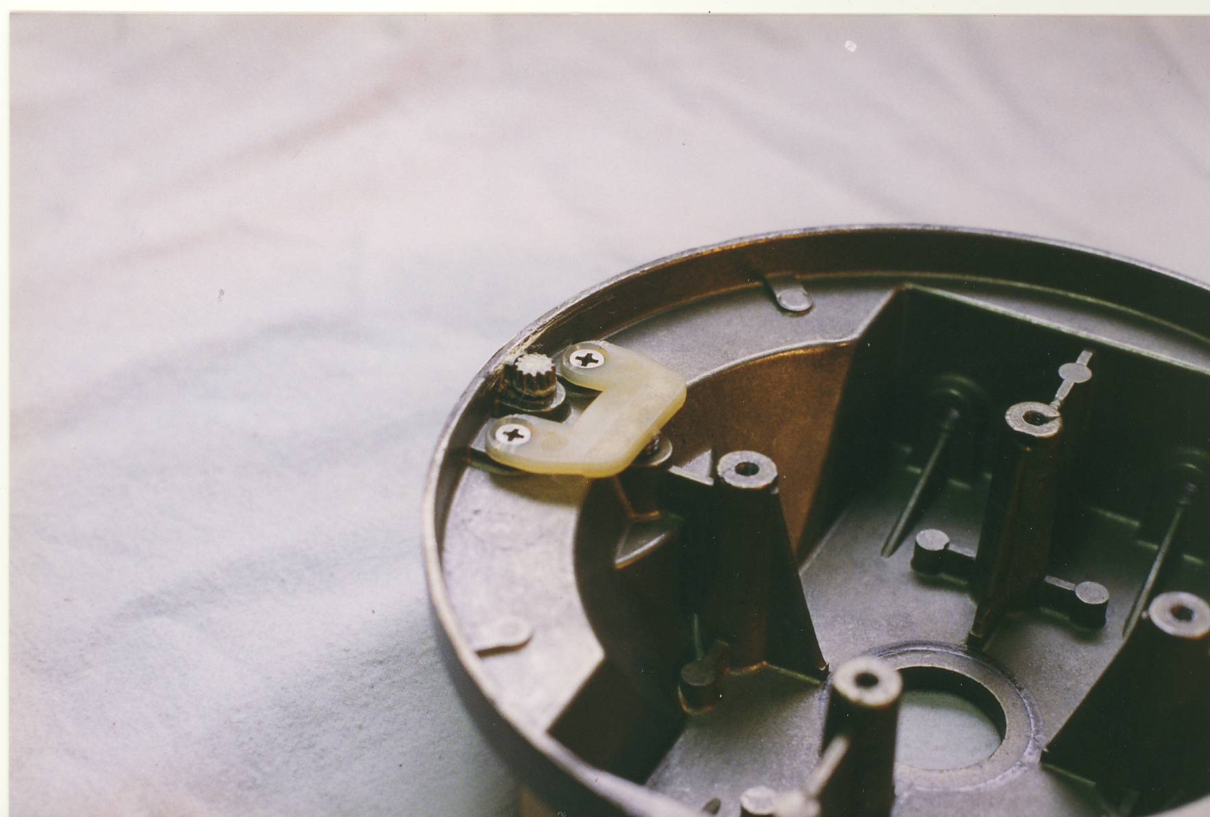
Located on the top plate is the RA slow motion spur gear and brake pad. Check this for wear and replace as needed. Keep any grease off this pad or you will have slippage when locking down the RA.
Disassemble the setting circle unit but be aware that there is a spring inside that will probably jump out as you take it apart! This spring allows the setting circle to slip while the telescope is turned in RA. If the spring is not positioned correctly, the circle will drag when the scope is turned and your pointing accuracy will suffer greatly.
Remove the 3 screws holding the setting circle assembly together and you will probably have a spring jump out at you. Here are all the pieces separated.
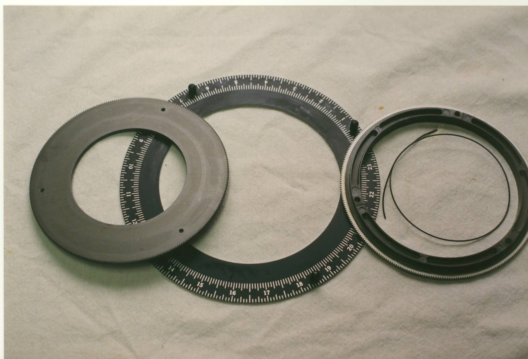 >
>
This is a good time to clean all the grease and dirt off these components. Reassembly is pretty easy. Put the 3 main parts together and insert the 3 screws. Tighten enough so that everything holds together. Now, with the setting circle facing up, put the spring between the slow motion ring gear and the setting circle. Just stick one end under the ring gear unit and feed the rest of the spring around and under the gear unit.
Make sure all the sliding faces have a thin coating of grease to allow them to move freely against each other or, as you swing your scope in RA, the circle will bind and turn and will not properly show right ascension. Once the scope is back together, you can check this by loosening the RA lock and swinging the scope around. The RA circle should not move while you do this.
Reassemble in the reverse order of disassembly. Apply a light silicone or lithium grease to the moving parts. I put a dab of grease on the slow motion spur gear; a dab on the spur gears on each drive motor and a thin film on the slow motion and drive ring gears. Lubricate the shoulder on the polar axis where the RA circle assembly rests.