 Steppers
and circuit board awaiting wiring.
Steppers
and circuit board awaiting wiring.|
I have been working around electronics for many, many years in electro-mechanical and electronic telephone switching machines covering thousands of square feet and not small electronic assemblies. Being able to fix something is a far cry from being able to fabricate something! I'm a pretty good fixer, but this is my first real experience fabricating. When I stand in front of a parts bin full of connectors at an electronics store I am completely overwhelmed! How I am trying to do the electronic work here is just one of many approaches and is probably not even close to being the best one. If anyone has any suggestions on how to do things better, please don't hesitate to write. |
|
Please be aware that any time you are hooking up "foreign" components to your computer, you run the risk of letting out the magic smoke that every electronic circuit needs to function properly. Read EVERYTHING on Mel's page (and the listserv as well) before hooking up a circuit to your brand new $3000 laptop! |
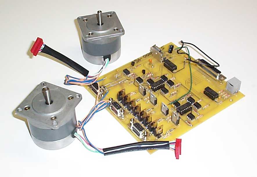
4/14 After a couple weeks, it's time to get back to work on the project. The big motivation is the circuit board and hand paddle have arrived from Mel. We had problems with the US Mail (so what else is new?) and the first board he sent has disappeared into the great beyond. Mel was kind enough to get a replacement board out in short order and it's now sitting on the workbench.
Steppers
and circuit board awaiting wiring.
The first order of business was to hook up power (a 6v lantern battery as recommended for the first time), connect the board to the computer and see if it responds to any of the various test modes Mel has added to SCOPE.EXE. The board, computer and cabling all seems to work! One test allows you to test the parallel port. You can use a voltmeter to watch the output part of the circuitry be driven high or low under computer control. Or you can set the program to scan the parallel port and by feeding +5v or ground to the test points, you can read the high or low signals back on the computer display.
Another test allows you to check the hand paddle to make sure all the switches and buttons can be read correctly through the parallel port. I'm VERY happy to report everything apparently is working just fine! Another test will let you step the motors and this is the one I really want to run! First, however, I need to connect the motors to the circuit board.
As you might be able to see in the above photo, the motors connect to the circuit board via female DB9 connectors. My plan is to use crimp-on connectors on the motor leads and the end of the cables that attach to the motors. These will also have a touch of solder just to make sure a good connection is obtained. The cable will have spade lugs while the motor leads will go to ring terminals. They will be joined on a pair of 6 terminal barrier strips.

Here you can see the motor leads have been crimped and soldered onto the ring terminals and secured to the barrier strip.
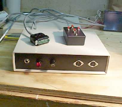
4/15 Everything has reached a stage where it is possible to run a test of the complete assembly. I have mounted the circuit board into a temporary project box, added a phono jack for power and wired in an on-off switch just to make it easier to kill power. Here's a picture of everything set up for testing:

Menu started out with the TEST TRACK mode. This will send a stream of pulses to the ALT motor and allow you to change some of the motor parameters. I put in a value of 1000 for the micro steps per second and chose the option that allows changing motor parameters. The motor made noise, but wasn't turning. Faced with a bewildering array of choice, I changed the MsDelayX option from 1 to 2 and the motor started turning! Feeling pretty good, I then changed the test option to Test2Motors and hooked up the AZ motor. Oops... the ALT motor continues to turn just fine, but the AZ motor is stalled. It is attempting to turn, but the shaft is just moving small amounts back and forth.
I have sent out a request for help to the listserv. Chuck Shaw responded with a suggestion that LEDs be wired up to each motor winding to give a visual indication of what's going on. Here is his response
|
If your motors are identical, it sounds like there is something wrong in the cabling to the Az motor.... You can try the LED hookup to watch and see if all 4 windings are getting pulsed . The LED hookup is simply 4 LED's that are wired to a motor plug. They each function as a winding. The +12v comes in to the "common" lead to a 1k resistor, then to the +leads of the LED's, and the negative leads of the LEDs then each return to the motor plug and via the cabling to the TIP120's and then to ground. Its such a cool light show I have added them to my mount permanently.....The az LEDs are red, the alt LEDs are green, and the Field rotator LED's are yellow. If one of your LEDs; is NOT lighting up, you may have a bad solder joint, or something wired backwards (or one of the optoisolators installed backwards, etc..... I wrote up some words for using the parallel port test to "trace" the signal from the laptop to the windings, and Mel put it on his website.... The LED writeup is there too. Its undoubtably something simple..... Just have to trace it out... |
Looks like it's time for another trip to Radio Shack.
4/17 While I didn't make the trip to Rat Shack yet, I did manage to find the problem with the motor. Seems that pin 6 of the AZ DB9 connector was not making contact with the solder on the backplane. Pins 5, 6, 7, 8 and 9 are all tied together to the +12v battery (or whatever supply you are using to power the motors). All the pins but 6 were soldered well into place. Hit the circuit trace with a small soldering iron and everything started working well. Spent most of today playing with the steppers and the SCOPE.EXE program. Chuck Shaw has written up a technique to use when trying to smooth the motion to your motors and that's what I was playing with. You can find it on the Scopedrive list right here. What I am finding out is there is a TON of information out there about how to build Mel's system and configure everything to work. The problem is that it is posted all over the Internet and in no real coherent format. Seems like I spend 5 minutes testing and 2 hours digging on the Web for each step!
Using Chuck's procedure, I have gotten the motors turning fairly smoothly, but have not yet started working on the PWM section. My main goal was to get the current draw down to a reasonable level. When I first turned on tracking, the circuit and motors were pulling more than 1.2 amps. Initial playing has dropped this to a much more reasonable .38A. The circuit board alone is pulling about .18 amps (180ma) so this means the motors (rated at .85A at 6V are drawing a total of 200ma. During HS slew this goes up to 600ma or so.
WARNING: Do NOT disconnect or power down your computer from the circuit board if the board power is still applied! I was swapping out DB25 cables while the circuit board was powered up and saw the current draw kicked to over 8 AMPS! Fortunately, nothing smoked, but you can believe I hit the power switch - QUICK - when I saw that!
I'm still reading all the documentation on Mel's site and trying to find applicable messages in the Scopedrive listserv. There is still a lot of work to do on the electronics. I need to run the DB9 connectors to something on the face of the project box for easy connect/disconnect of the motors. Will be taking a drive out to Austin Electronics tomorrow to see if they have any interesting connectors.
4/25 I decided to use DIN 5 connectors between the electronics box and the motors. Would have used DIN 6, but Austin didn't have any panel mounts. The 5 connectors work because the 2 windings both use a common source of 12VDC. Just ran a single conductor to the barrier strips and then jumpered the 2 hot leads together. The final product didn't turn out too badly! Here's a picture:
Except for possibly having to cut the cable lengths (I have 10 feet for each motor), the electronics part of the project is complete and made vastly more simple by just buying Mel's board! I'm still not sure how everything is going to go together on the scope. I have seen a picture where one builder added a table to the side of his rocker box. It sat up around waist level with a wooden dew cover over it. The laptop and electronics would ride on this table and it helped keep cables short and prevented tangling. My usual setup is to keep the laptop and books inside the back of my van. I cobbled together a quickie table out of a piece of half inch ply and some 1" PVC pipe and fittings. This keeps observing paraphernalia dry, and is a possible solution. The problem here, of course, is all the cables stretching from the back of the van to the telescope. I know I'll trip over them at least 5 or 6 times a night.
It's a problem to be solved somewhere down the road. Right now, I hope to have "first slew" sometime this weekend if Harry and I can come up with a good method of mounting the motors. Will keep you posted.