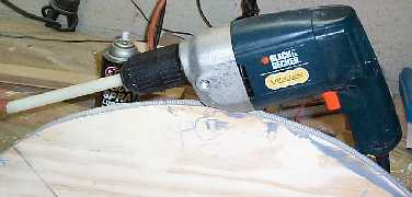
The first testing opportunity came when I took a short piece of the threaded nylon rod, chucked it in a 1/2" electric drill and tried to turn the azimuth gear. The gear turned!
It also became obvious that the teeth on the edge of the wheel were too deep. Here's a representation of the situation.
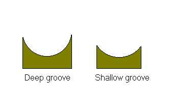
Since we are not cutting these gears into metal using metal tools, the JB Weld, nylon and wood all have the ability to expand and contract during and after the the casting process. The result is that if we press the nylon rod into the teeth, there is enough friction because of this expansion/contraction that the rod will be held in place. When turning the rod and gear, this additional friction will have to be overcome by the stepper motors. The easiest solution will be to grind down the edge of the deep groove until it looks like the shallow groove.
Because the gear is not perfectly round (I don't think it's round to within an 1/16th or even 1/8th of an inch!), there are sections where the groove is shallow. The ease of turning the worm at this part is evident and the increase of friction when reaching a deep part of the groove can also be easily felt by turning the rod by hand. The drill has more than enough torque to turn the rod under any conditions.
My plan here is to use the small jack plane to shave off another 1/16 of an inch or so of the edge of the gear wherever the threaded rod is held in place by friction. If this becomes too big a job, I will try doing the reduction using Harry's belt sander rigged up in a jig to allow controlled feeding of the edge to the sander. Will let you know how it all turns out.
5/13 Most of the work this past week has been spent in testing. I was reaching the point where I was going to mount the altitude motor, but before doing that, had been reading the messages in scope-drive about smoothing out micro stepping by mapping your micro steps with a laser pointer and graphing them in Excel. Sounded like fun, so I picked up a cheap pointer and gave it a shot. What a mess that turned out to be! The software is configured for 20 micro steps per full step and at the distance I was projecting the laser, this worked out to right around 160mm per full step, so.... each micro step should have been right around 8mm (8mm * 20 micro steps = 160mm). Not even close! The first few micro steps started out at about 4-5mm and got smaller and smaller until there was a giant step of more than 60mm at step 14. Obviously time to head back to the drawing board.
After a couple messages to the scope-drive list and a couple private mails, it was obvious that my original playing around with the motors to set micro stepping had been completely off. When people talk about adjusting parameters to get the motion of the motor as smooth as possible, that means the motor should rotate smoothly with almost no detectable stepping action visible. Well, dammit, it's a stepper motor and I was looking for smooth stepping action while keeping the current draw low. The list quickly pointed out my errors and let me know I was looking for smooth rotation. Finding this magic point requires a lot of time setting the MsDelayX and PWM while running MSPause up and down the scale while observing the rotation of a pointer fastened to the shaft of the motor. It has also helped to have the azimuth motor mounted and driving the gear since you can tell smoothness by the sound of this motor. As you play with MSPause, I can hear the az motor turning more and more roughly and then smoothly as the values change. I am using the sound of that motor and the visual appearance of the pointer on the alt motor to make my adjustments. So far I have located several sweet spots where things seem pretty smooth and current draw is down fairly low. Probably have another couple hours of testing before the best spot is located and then I'll try the laser pointer again to see how it all works.
For today, however, I've removed the ground board and will give it a coat of paint. I've decided, for now, to leave the JB Weld gear on the ground board alone. Playing with the motor mounting angle and the spring tension make it possible to get pretty smooth tracking and slewing motion out of this gear. I was planning on shaving off a bit of wood at the point where the groove was deepest since the worm didn't appear to make good contact with the wheel in this area. A little more spring tension might overcome this problem without causing the motor to stall at other parts of the gear.
5/14 First azimuth slew today with the whole telescope assembled! Just for fun, I hooked up two 12 volt batteries and drove the scope with 24v. Slew speed was 3.7 degrees per second! This was with MINDELAY variable set down around 250 or so. I was running at 450 with a single 12v battery and getting a bit less than 2 degrees per second.
9/4 Thought I would use this section of the web page since the scope is finally at the testing stage. It's been awhile since the last update, so let me bring you up to date on what's going on.
As you may have read on the Motors page, the new motor mounts are complete and working satisfactorily. Much of the friction and attendant motor stalling has been eliminated with a dry Teflon spray lubricant that I found in a local bicycle shop. It leaves a coating of Teflon on the JB Weld gears and works very well.
The big accomplishment has been getting the encoders and Advanced Astromaster box working with the SCOPE.EXE software. I bought an RJ-11 to DB-9 cable for connecting a computer to the AAM box months ago, but never played with it beyond one try at the 2000 Peach State Star Party. Couldn't get the computer and encoders to talk to each other, so the project was back burned for awhile. Encoders really provide the finishing touch to a motorized telescope since they give positive feedback of where the telescope is really pointing. If you have stalling problems (as I do on occasion), it's a nice feature to have the encoders reset the software.
At least that's the theory! The first problem was getting the computer to see the encoders. A few minutes with an ohmmeter showed that the cable was wired completely backwards. Fixing that was a simple matter of cutting off the RJ-11 and crimping on a new one with the wires oriented properly. Plugged everything up and SCOPE.EXE could read the encoders.
One of the nice features of the software is the ability to use encoder counts to set the full step size variable. This is set to the distance the scope will move on one full step of the stepper motors. As a memory jog: you multiply the number of steps per rotation of your stepper by the final drive ratio and divide that answer into the number of arc seconds in a circle. My computation was as follows: the az gear is approximately 25.5 inches in diameter or just a touch over 80 inches in circumference. The threaded rod made a gear with 13 teeth per inch, so the final drive ration should be 80 x 13 = 1040:1. Driving this with a 200 step motor and with 1,296,000 arc seconds per full circle, we end up with 1,296,000/(1040x200) or about 6.23 arc seconds per full step. Realizing that the the diameter of the gear is just an approximation, we shouldn't be surprised if the full step size is a bit different.
Once I had the encoders working, the first thing I did was to do a half-step move of 25,000 half steps and then checked to see how close my calculated value matched the computed value from the encoders. Hmmm.... the values the program was showing were all a bit short and seemed to be clustering around 5.96 or so. Now working backwards a 5.96 gives a gear ratio of about 1087:1 and, going back a bit more, a gear diameter (at 13 threads per inch) of 26.6 inches. Now, the gear is sitting right in front of me and I've measured it 14 ways from Sunday and I KNOW the bloody thing is not more than 26 inches in diameter!
Expecting the encoders were telling the truth (they have always been very accurate when mounted on the telescope as digital setting circles), I accepted the value and repeated moves of differing numbers of half steps until I had data on more than 50 moves. Plotted them on a spreadsheet, calculated mean and average and came up with a full step size of 5.96176 arc seconds. Plugged this value into the software for full step size and tried turning the scope in a 360 degree circle in azimuth with a laser pointer taped to the rocker box. Of course, it didn't even come close to turning the full circle. Scope probably stopped moving a good 5 degrees from completing the circle.
Without going through all the hair pulling... I had the encoder counts set wrong in CONFIG.DAT. It was set for 4096 count encoders and I have 4000 count. After correcting that, I started making 360 degree circles with the scope and laser pointer to set the gear ratio as accurately as possible. After a couple hours, it turned out to be 6.14509 arc seconds per full step or much closer to my calculated value of 6.1445 - a most gratifying fit. The encoders also tracked the scope movement well within the error range of the encoders. The best accuracy you should hope to obtain from 4000 count encoders is 1296000/4000 or about 324 arc seconds or 5.4 arc minutes. I set the software to do an encoder reset if the calculated position of the scope varies by more than .75 degrees from the position shown by the encoders and during several hours of playing, there was never a reset in azimuth!
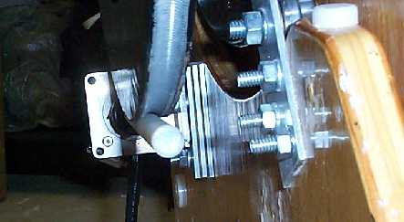
The next problem was noise reduction and I came up with a very simple and inexpensive sound deadening material - a mouse pad! My altitude motor was still pretty noisy, so I put a piece of mouse pad between the stack of aluminum and cork material and the rocker box. It was necessary to remove one piece of aluminum from the stack (you can see the 3 pieces here) in order to accommodate the thickness of the mouse pad material, but there was a very significant reduction in noise. The az motor fairly quiet, so with the reduced altitude noise, the scope is ready to hit the field and see if it works.
The final problem was one of balance and I'm still working on this one. Rick Singmaster builds his scopes with the center of gravity (my thanks to Tom Krajci for his kind explanation of all this!) located below the center of the altitude bearings. With a 35mm Panoptic, Paracorr, shroud and Telrad, the scope comes to its natural point of equilibrium pointing at about 45 degrees elevation. Rick then adds some felt pads to the rocker box to provide a bit of friction against the mirror box and the scope is able to hold its position with any eyepiece without changing counterweights as is necessary with some Dobbies. However, having the scope out of balance as it approached 0 and 90 degrees of altitude threw a strain on the altitude drive motor. Tom uploaded a picture of the situation to the scope-drive list, and you might look in the files section for it to see what is being discussed. Tom's suggestion was to mount some weight above the center of gravity and this is what I am working on now. It looks like 6 or 7 pounds of dive weights mounted about 13 inches above the top of the altitude gear will give pretty good balance throughout the altitude motion of the scope. Unfortunately, I have all this weight hanging off a piece of 1x2 that is bolted to the side of the altitude bearing! Not only is it as ugly as sin, it has a tendency to vibrate as the scope is moved. Work on a more permanent and less ugly mounting is underway.
I apologize to my Gentle Readers for taking so long with all this! It had been my hope for under the star testing in August, but the rain in Georgia as well as some family issues got in the way of such a test. Now we are heading to Europe for 2 weeks, so any possibility of a test will have to wait until the weekend of 9/29. With the encoders hooked up to correct the scope's position if the motors stall, I am very confident that we will have a working scope!