8/5 Some of you may recall that this section showed some pictures of wooden couplers I had planned on trying to use to join the motor shafts to the nylon rod. This page obviously wasn't going anywhere, so thought I would take it over to show the latest approach to mounting the motors and coupling them to the nylon rod.
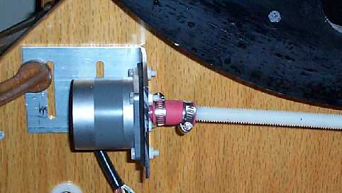
When the system was given its initial test, one of the big problems was that the rubber hose and clamps used to secure the nylon rod to the motor shaft was not sufficient to hold the rod straight. The rod itself had a bit of a bend in it and the combination caused the rod to wobble while it turned the gears. This imparted a jerky motion to the telescope. Another problem was the fact that the thin aluminum motor mounting brackets were very difficult to adjust. The rod needs to be parallel to the center line of the gear and it needs to be centered on the edge of the gear. It was impossible to easily make these adjustments and the motion of the telescope suffered greatly as a result. Finally, the mounting plates were large and flimsy. Made out of 1/16th inch aluminum, the plate probably contributed to the noise of the motors. Here's a picture of the original motor mount with hose and clamps holding the threaded rod to the motor shaft.
And now a picture of the latest incarnation:
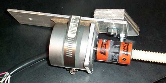
First thing, notice the Lovejoy coupler.
These are available from MSC
as three separate pieces: the central rubber spider and two end
pieces bored out to accommodate the desired size shaft. You may
notice the gray of JB Weld! Because the shaft will only be supported
on the motor end, it was necessary to JB Weld the pieces together
or the couplings would fall apart. If you have a shaft supported
on both ends where the shaft can not slip away from the motor,
it won't be necessary to glue everything. As you can see the motor
is held to a 1/16" thick aluminum plate with nothing more
than a large hose clamp. Between the motor and the plate is a
piece of the cork gasket material I'm trying out for sound dampening.
The hose clamp provides a very rigid and very simple method of
mounting the motor. The motor mount plate is bolted to a stack
of three 1/16" pieces of aluminum separated with a piece
of cork for nose suppression. Here's what the finished piece looks
like mounted on the rocker box.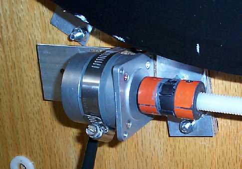 The stack of aluminum is held to the rocker box by the bottom
bolt and the center, pivot bolt. The motor plate is able to pivot
up and down to engage and disengage the threaded rod from the
altitude gear. By adding or removing aluminum plates and cork
from the stack, it is possible to closely align the rod with the
gear. Because the stack fits flat against the rocker box and the
motor plate is parallel to the box, the rod travels in a path
- as it is pivoted - closely parallel to the face of the gear.
The stack of aluminum is held to the rocker box by the bottom
bolt and the center, pivot bolt. The motor plate is able to pivot
up and down to engage and disengage the threaded rod from the
altitude gear. By adding or removing aluminum plates and cork
from the stack, it is possible to closely align the rod with the
gear. Because the stack fits flat against the rocker box and the
motor plate is parallel to the box, the rod travels in a path
- as it is pivoted - closely parallel to the face of the gear.
The back end of the motor plate extends beyond the back of the motor about 2 1/2 inches. This is presently unsupported, but my plan is to fasten either a piece of wood with Teflon or aluminum plates under this end to give the motor plate something to ride on as it pivots. My plan is to use a spring pulling down on the far end of the motor plate to press the nylon rod into contact with the
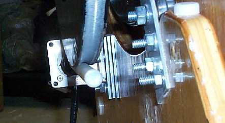 Here is a picture looking down
on the motor mount. The aluminum plate with four bolts in it is
one of the altitude bearing support plates. You can see the two
layers of cork as dark separators between the three aluminum plates.
Here is a picture looking down
on the motor mount. The aluminum plate with four bolts in it is
one of the altitude bearing support plates. You can see the two
layers of cork as dark separators between the three aluminum plates.
Even though I have not yet tested these new motor mounts, I am far happier with them then I was with the old ones. There is a feeling of being able to control the nylon rod's position to the gear. Also, there is almost no flexing with the new mounts and everything has a very solid look and feel.
Will have some pictures of the azimuth mount in another couple days. Hope to work out the spring arrangement for holding the nylon rod in contact with the gear over the next week. I'm STILL tweaking the blasted PWMs for microstepping! Just don't have the patience to spend several hours doing the job right, but will need to - probably next weekend.
After the disappointments of the first trial, it feels like progress is being made again! I hope to give the scope a trial next weekend (8/12) or the weekend afterwards.
A similar mount is being built for the azimuth motor.
8/12 The motors are mounted back on the telescope and
it's almost time to test the system indoors. I did try running
the motors in tracking mode and they are MUCH quieter than the
original installation! Not as quiet as the first motor mounts
with everything mounted on foam, but quieter than the first trial.
It looks like the rubber and cork gasket material makes a useful
noise dampening material. The altitude motor seems to be making
the most noise. If the system works this time around, will spend
some time attempting to silence the setup and decrease vibration.
Here's a picture of both motors mounted on the rocker box. The
spring hanging down from the altitude motor will be used to force
the threaded rod into engagement with the 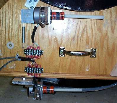 gear.
The spring that shows up in the picture is a bit too light to
do the job. It's one I picked up just to give a starting point.
During testing, I pulled the spring all the way down to the bottom
of the rocker box and the scope moved very smoothly in altitude!
The shorter and straighter rod sections did not cause the bobbing
motion in altitude I had experienced with the old motor mounts.
gear.
The spring that shows up in the picture is a bit too light to
do the job. It's one I picked up just to give a starting point.
During testing, I pulled the spring all the way down to the bottom
of the rocker box and the scope moved very smoothly in altitude!
The shorter and straighter rod sections did not cause the bobbing
motion in altitude I had experienced with the old motor mounts.
 The picture here shows a close up
of the azimuth motor. You can see the cork wrapped around the motor
and the hose clamp securing the motor to the aluminum plate.
Just to the left of the motor and partially hidden by the wires
coming out of the motor you can make out the nut on the pivot
bolt. On the right side of the image you will see one of the azimuth
bearing assemblies. The top mounting plate for the motor has been
changed since this image was taken. It now extends about 1/2"
beyond the front plate of the motor and has a hole drilled at
the outer most corner. Through this hole is a #8 machine screw
that will serve to anchor the spring that will engage the rod.
A hook has been screwed into the bottom of the rocker box for
the other anchor point. Pictures will be posted in another couple
of days.
The picture here shows a close up
of the azimuth motor. You can see the cork wrapped around the motor
and the hose clamp securing the motor to the aluminum plate.
Just to the left of the motor and partially hidden by the wires
coming out of the motor you can make out the nut on the pivot
bolt. On the right side of the image you will see one of the azimuth
bearing assemblies. The top mounting plate for the motor has been
changed since this image was taken. It now extends about 1/2"
beyond the front plate of the motor and has a hole drilled at
the outer most corner. Through this hole is a #8 machine screw
that will serve to anchor the spring that will engage the rod.
A hook has been screwed into the bottom of the rocker box for
the other anchor point. Pictures will be posted in another couple
of days.
As in the case of the altitude spring, I need a "stronger" spring to keep the azimuth rod engaged with the gear. Again, motion is pretty smooth, but when the rod is turning so that the direction of movement is towards the motor (turning clockwise in the image above), the rod has a tendency to ride out of the JB Weld gear. Just a bit of finger pressure against the motor seems to keep everything in contact, so need to pick up another heavier spring. Again, hope to have some pictures posted in a couple days.
Overall, I am extremely pleased with the new motor mounts! They are very simple, sturdy and quieter than the original mounts. It's my hope to find the proper springs this week and to take the scope out for the next round of testing next weekend. Noise does remain a bit of a problem, but it's not nearly as bad as it was with the first mounts! Scope motion is vastly smoother than it was with the other mounts. I expect getting the rocker box riding on ball bearings had a lot to do with the improved azimuth motion.