05/06 I know it goes against conventional wisdom, but it looks like the Teflon on Formica is working for the bottom of the rocker box! At least, it is so far without the weight of the telescope itself being added to the mass that has to be moved.
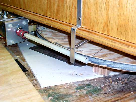
As you may have guessed from the above statement, the azimuth motor has successfully moved the rocker box around in a circle. A lot has happened over the past couple days working on the scope, so I better fill you all in. Here's a picture showing where we are right now.
This picture gives a good overall view of how I have attempted to drive the scope in azimuth. Everything has not gone smoothly and the bent aluminum piece in the center of the picture is a first effort to provide some inward force to keep the threaded rod engaged with the JB Weld gear. The motor mount is attached to another aluminum plate that is bolted through the bottom of the rocker box. The bottom side looks like this:
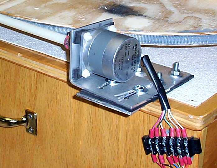
Got everything hooked up and started the first 360 degree rotation of the rocker box. It didn't go very far! If you look at the above image, you can see that the motor mount is slotted. This lets me change the angle at which the rod engages the ground board. It turns out this is a fairly fussy adjustment: too sharp and the motor binds. Too shallow and the rod loses engagement and slips. It was at this point that the idea of putting some pressure against the rod with the piece of aluminum and a spring came to me. This sort of works. I might try putting another pressure plate between the motor and where the threaded rod engages. The binding of the motor was pretty much eliminated by dropped the half-stepping rate (you will have to get into Mel's software to learn how it is configured) from 425 to 500 for MINDELAY variable.
There is one really bad sector on the gear that may end up causing a lot of trouble. If you recall, there were a couple places where the plywood broke away when pulling the threaded rod free from the JB Weld. The threaded rod has a tendency to want to jump out of engagement at this point. I think a bit more pressure against the rod will help reduce this problem. There is also a section of the ground board where the JB Weld gear is a bit deeper than other places. The rod does not engage here well at all and it will probably be necessary to take the groove sides down a bit to help problem.
To use this, you rotate the scope a full 360 degrees. Mel's software will tell you how far it thinks it has moved. I estimated my full step size would be somewhere in the vicinity of 6.1 arc seconds per full step. I left the CONFIG.DAT file to the 5 arc seconds that Mel uses as a default. Running the box around a full rotation and doing the calculation, my full step size worked out to 6.1445 arc sec/step - gratifyingly close to my calculation!
Now I need to do a bit of work on the depth of the groove on the ground board to try to get a bit better engagement. I will also add a second pressure bar to see if that helps keep the rod engaged with the gear. Still not sure if pressure will be sufficient to overcome the broken out part of the ground board. If worst comes to worst, I can just point this part of the ground board to some part of the horizon where I will not be observing and set the computer and battery at that location. It's probably no more than 10-15 degrees and I tend to work one area of the sky at night. Hey, it's a rationalization, right? Once I get a dependable motion of the rocker box, it will be time to mount the altitude motor and start working on that project.