5/17 It has been another series of frustrating days! I had been hoping to have the scope ready for first slew by tonight, but, rather, I'm going back to square 1 with the altitude assembly. Here's what's been happening.
The plan had been to use smaller versions
of the rollers that didn't work for the azimuth bearings. If you
recall, I had hoped to use these bearings: Forget it! I know Mel
has this picture on his home page, but the things just do not
work for a larger telescope.
| It's my suspicion that these things load down too badly under some weight and they lose all smoothness of rotation when the weight of the scope presses down on them. Not that they are very smooth to start, but they drag like crazy when you put a few pounds load on them. After my experience trying to use them for the az bearings and, now, the same experience for the altitude... the things have been pitched into the trash! They might work on an 8" scope, but they do not work at all on a 16! |
I started out by applying the 1/2" wide aluminum strips over the Formica altitude bearing surface. This was a pretty easy job and shouldn't cause any surprises. One strip went down tight enough that the screws at each end were sufficient to hold it in place. The second strip was a bit looser and I need to drill and countersink a small hole halfway between the ends and put in a small screw. The top of the screw will have to be flush with the aluminum to prevent a rough spot. Here are some pictures that will help you visualize what's going on.
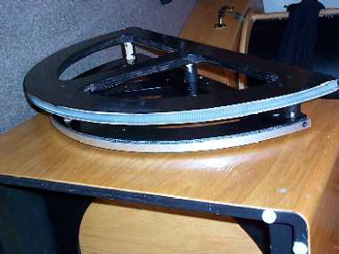 Here
you can see the aluminum strip on the alt bearing below the altitude
drive gear. The screw holding on this side is visible at the right
end of the strip.
Here
you can see the aluminum strip on the alt bearing below the altitude
drive gear. The screw holding on this side is visible at the right
end of the strip.
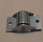
Here's one of those bloody bearings (HA!) mounted on the side of the rocker box with the altitude D bearing pressing down on it. You will notice that the bearing is not mounted flush against the rocker box, but is sitting up on short spacers. I had planned on mounting them flush by filing out a small recess in the rocker box to accommodate the bottom part of the roller. Fortunately, I had decided to wait to see how well the bearings worked before taking a file to the rocker box!
The Next Plan: I went down to Target and bought 2 tubes (16) of inline skate bearings for $15.00. These have a 5/16th inch central hole and very smooth motion. Then down to Home Depot to pick up 1 1/2" 5/16th inch hex head bolts, washers, nylon washers, lock washers and nuts. Also picked up a 48" strip of 1 1/2" wide and 1/8th inch thick aluminum flat stock. Out of all this, I hope to fabricate some bearing holders. It would be nice to be able to use a piece of aluminum stock at each end of the machine bolts, but there is very little clearance between the rocker and mirror box. Here's a picture of what I have come up with.
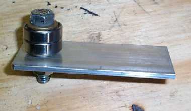
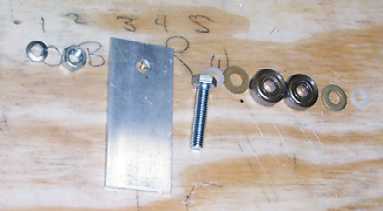
Two bearings with 2 flat washers (small) and 2 nylon washers give me just about 3/4" thickness of the sidewalls of the rocker box. The washers keep the bearings from being crushed when you tighten down on the machine bolt. It's my hope that a single mounting plate will provide enough stability. The question I am trying to answer now is should the bearing assembly be dropped down an inch or so from where you can see the hole in the aluminum. The reason for this would be that the aluminum plate would act as a stop to keep the altitude bearings (and mirror box) from sliding from side to side. Some people have mounted ball bearings horizontally to press against the D bearings to accomplish the same task. You can see a picture of this on Chuck Shaw's page. Not sure which way I will go and if anyone has any suggestions, would enjoy hearing them.
Once I get smooth motion of the scope in altitude, it will be time to mount the alt. motor and see how well that works. This may not happen until June. I'm starting a long work stretch and then we are going up to Columbus, Ohio for 2 weddings. Probably will not have much of a chance to work on the scope for the next 2 or 3 weeks.
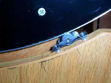
5/18 Got the altitude bearings mounted this evening and the difference in motion between the bearings shown above and the inline skate bearings is incredible! The bearings are mounted as shown in the picture. Here's a closeup of one of the new bearing assemblies mounted on the rocker box.
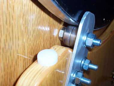
As you can clearly see, there isn't enough room between the head of the bearing support bolt and the side of the mirror box to allow supporting the bearing on both inside and outside the rocker box. The 1/4" x 20 screws used to hold the bearing assembly in place are 1 1/2 inch and a bit long. I'll replace them with 1 1/4 inch screws before completing the project. Here's a closeup without the mirror box.
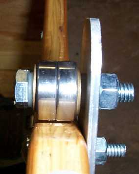 The bearing sits 1/16" of
an inch above the side of the rocker box. The only thing that
might go wrong is the 1/8th inch thick aluminum plate may bend
with the full weight of the telescope pressing down. This will
be instantly obvious by a closing of the small gap between bearing
and rocker box. Should this be the case, it's planned to replace
the aluminum with 1/8" stainless steel plate. The telescope
tube assembly weighs right around 80-85 pounds so the loading
on each bearing will only be about 20 pounds. The aluminum plate
should hold up without deforming (fingers crossed!)
The bearing sits 1/16" of
an inch above the side of the rocker box. The only thing that
might go wrong is the 1/8th inch thick aluminum plate may bend
with the full weight of the telescope pressing down. This will
be instantly obvious by a closing of the small gap between bearing
and rocker box. Should this be the case, it's planned to replace
the aluminum with 1/8" stainless steel plate. The telescope
tube assembly weighs right around 80-85 pounds so the loading
on each bearing will only be about 20 pounds. The aluminum plate
should hold up without deforming (fingers crossed!)
Next on the agenda will be attempting to get the scope to move in altitude.
5/19 The new bearings work like a champ! Used a C clamp to hold the altitude motor in place and the scope moved up and down perfectly! Well, almost perfectly. Looks like I'll need to add a bit of weight to the nose piece of the scope. Even with the 35mm Panoptic and Paracorr, the scope is still a bit mirror end heavy. Once the Telrad is in place, should not need more than a pound to give the necessary weight to balance out the scope.
There is also a need to provide some pressure against the threaded rod as it sits in the altitude gear. I suspect this will be less of a problem than the az gear (the spring loaded aluminum strip, if you recall) and all it will take is a Teflon block pressed against the rod with a screw holding the block in place. Not sure how this will be accomplished yet. The azimuth assembly is still problematic. The thin aluminum strip and spring have a tendency to bend providing varying amounts of pressure. Something a bit more substantial is required to give a controlled amount of pressure against the azimuth threaded rod.
Once the altitude motor is permanently mounted and the tensioning rigs worked out, the scope should be ready for its first test under the stars. I can see where there will be a lot of fine tuning required before taking the scope out to its first observing session, however. Tops on the list will be making the damn thing quiet! The whole rocker box is acting as a sounding board and the motors, when in tracking mode, are VERY noisy! When I say noisy, I mean an LX200 at full throttle is a whisper compared to the present noise level! The rubber I've been using does not seem to work well for sound dampening, so plan on trying other materials. Slewing does not make anywhere near the noise of tracking and the solution will probably be a combination of sound deadening material and final software tweaking of the configuration file.