Mechanical Assemblies
- Part 5
6/4 Time
to get back to work on the scope. I had hoped to take it out for
it's first "under the stars" test Friday night, but
too many other things got in the way and it will have to wait.
My two big projects have been mounting the altitude drive motor
and trying to get the scope to quiet down. As I said, an LX200
moving flat out is dead quiet compared to how these steppers sound!
Here's a picture of the alt motor mounted on the rocker box. All
the gray-black stuff around it and the screws is foam rubber that
I'm using for sound dampening.
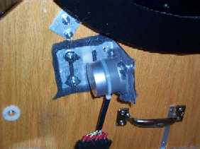 I don't
yet have the nylon rod attached to the motor. The foam, while
as ugly as sin, has provided very effective sound deadening. When
micro stepping, the motor is much quieter than it was before.
Not exactly silent, but very tolerable from the eyepiece position.
I don't
yet have the nylon rod attached to the motor. The foam, while
as ugly as sin, has provided very effective sound deadening. When
micro stepping, the motor is much quieter than it was before.
Not exactly silent, but very tolerable from the eyepiece position.
The next problem had to do with the balance
of the telescope. The scope is perfectly balanced with a Paracorr
and 35mm Panoptic when pointing at 45 degrees altitude. Push it
up or down and it wants to return to this home position. The nylon
rod pushed into the gear is more than enough friction to hold
the scope in any position. The problem that came up, however,
is that the force of the telescope pushing down as the scope nears
the vertical combined with the slippage of the rubber hose and
clamp against the motor shaft would cause the rubber hose to slip
off the shaft. Because the telescope wants to move downwards,
this is acting as a strong force pulling the nylon rod and hose
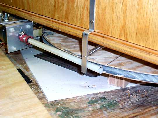
coupling off the motor shaft. The solution to this problem was
an end plate pushing against the end of the threaded rod. I also
made a block of wood with a threaded insert that is screwed to
the rocker box. There is a 1/4x20 bolt screwed into the threaded
insert that presses against a thin piece of aluminum and this
metal pushes against the altitude rod holding it in contact with
the altitude gear. Here's a picture of the whole assembly.
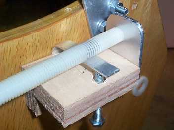 The
rod pressing against the aluminum plate provides enough force
to keep the hose coupling from coming off the motor shaft. There
is still a tendency for the hose to slip on the shaft as the scope
nears the vertical. This was eliminated by configuring the software
to not go above 85 degrees of altitude. This is not a major loss
since it represents "Dobson's Hole" familiar to all
Dobsonian users. If something is in the hole, wait 15 minutes
and it will move far enough to be accessible while still close
to the zenith.
The
rod pressing against the aluminum plate provides enough force
to keep the hose coupling from coming off the motor shaft. There
is still a tendency for the hose to slip on the shaft as the scope
nears the vertical. This was eliminated by configuring the software
to not go above 85 degrees of altitude. This is not a major loss
since it represents "Dobson's Hole" familiar to all
Dobsonian users. If something is in the hole, wait 15 minutes
and it will move far enough to be accessible while still close
to the zenith.
The bolt putting pressure against the
aluminum strip and then against the threaded rod has worked out
very well to keep the rod from jumping out of the gear. Another
similar rig will be built to serve the same purpose on the az
rod.
7/9 Not
much good news to report at this time. I finally got the scope
out for its first test under the stars and the performance of
the drive system was poor. Before we get into that, here's the
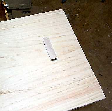
latest additions to the scope. In an effort to keep the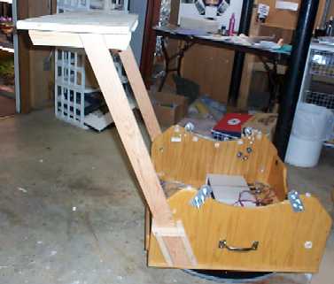 number of cable trailing off the scope and over the ground, I
decided that mounting a table to the rocker box might be the way
to go. Main design criterion was that the table not require any
hardware to mount to the scope. Setting up the scope and drive
system will take enough time - just wanted something that "snapped"
together. Here is the result. As you can see, the table supports
are just dropped into mounting brackets on the rocker box. They
are supported by a lip about 1/4" wide where the side boards
mount on the bottom board (thanks Rick!) Two supports are screwed
and glued to these uprights. The table top has two holes cut into
it to allow it to drop down onto the support brackets.
number of cable trailing off the scope and over the ground, I
decided that mounting a table to the rocker box might be the way
to go. Main design criterion was that the table not require any
hardware to mount to the scope. Setting up the scope and drive
system will take enough time - just wanted something that "snapped"
together. Here is the result. As you can see, the table supports
are just dropped into mounting brackets on the rocker box. They
are supported by a lip about 1/4" wide where the side boards
mount on the bottom board (thanks Rick!) Two supports are screwed
and glued to these uprights. The table top has two holes cut into
it to allow it to drop down onto the support brackets.
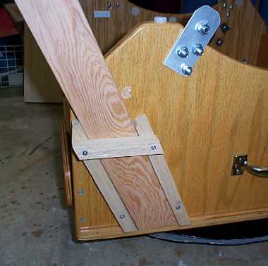
Here are a couple images showing the
mounting brackets on the rocker box and the top of the table with
the upright showing through the hole.
The Atlanta weather has been abominable
lately. Almost no rain, temperatures in the mid 90's, lots of
humidity and mosquitoes by the billions. In other words, the worst
imaginable weather for schlepping out almost 200 pounds of telescope,
drive system, 95 amp deep cycle battery and all the parts and
pieces needed for testing. My observing season usually ends in
June and starts up again in September when the weather has become
a bit more civilized, but it was time to face the hot July night
and see if any of this stuff actually worked.
Quick answer - not very well. Menu
indoors is a lot different than trying to put the system through
its paces outside. Even indoors the azimuth drive has been a bit
flaky with the motor stalling out. It is very sensitive in regards
to angle the threaded rod approaches the worm wheel and the amount
of pressure applied on the worm to the wheel. Get it just right
and it slews beautifully. Get either or both off just a bit and
the motor stalls or the rod jumps out of the JB Weld gear.
Setting the scope up on uneven ground
with grass turned into a disaster! Even with tweaking, it became
impossible to slew more than 45 degrees or so before the motor
stalled. The biggest problem was ground clearance. There is only
1 inch between the bottom of the motor mount and the ground (image).
The mounting plate was trying to push itself through the grass
as well as move the scope and it proved just too much for the
poor stepper. The backyard had been freshly mowed - nothing like
some of the observing fields where we set scopes up! In some cases,
the grass has been over 6 inches tall and would overwhelm the
drive system completely. I see two possible solutions - either
raise the base by increasing the height of the legs under the
ground board or picking up one of those plastic mats office chairs
roll on. Since it would be impossible to guess how deep grass
might be at some unknown observing field in the future, the mat
will probably be the easiest way to go. Drop the mat on the ground,
walk around stomping everything flat and then set the scope up.
Second problem is friction. The Teflon
on Formica feels very smooth in the shop, but once you get out
on uneven ground, it becomes obvious that Mel and the listserv
know best - ball bearings will be needed under the rocker box.
Someone (I have forgotten the name) came up with the idea of using
aluminum channel as a bearing support and that's the route I plan
on following. More pictures and information after a trip to the
hardware store.
Third problem is in altitude. The altitude
drive works much better than the azimuth drive. What's missing
is smoothness of motion during a slew. The scope sets up a rocking
up and down motion while slewing that needs to be investigated
and corrected. I suspect scope balance and flexing in the altitude
drive system to be the root causes. Flexing is a problem because
the motors are not mounted firmly, but are "floating"
on a bed of foam rubber for noise reduction. This adds flexing
to the system while making parts alignment difficult as well.
Next trip will also include a stop at AutoZone for some cork gasket
material to see if cork can provide noise reduction while keeping
parts in alignment.
The final problem was with the motor's
microstepping. No matter how I have set my PWM values, I seem
to end up with a bunch of little steps and one big step during
one complete microstepping cycle. This big jump was quite apparent
and objectionable at the eyepiece. Mel's latest software version
(7/7/2000) appears to offer a tuning solution where you can use
the + and - keys to make single microsteps and the ability for
the software to double the number of steps while making the PWM
interpolation. I'll be giving this a try over the next few days
to see if I can smooth out the motor motions. Mel's other suggestion
was to try other steppers. He had run into motors that just didn't
microstep smoothly and finally replaced them.
The scope is back in the work room and
I'll keep everyone posted about progress towards version 2.
Mechanical 4 Home Mechanical 6